The Zetasizer Nano uses dynamic light scattering (DLS) to measure hydrodynamic size of molecules and particles freely diffusing in solution. Measurements are typically performed using a cuvette-based batch method. However, the Zetasizer can also be connected to a size-exclusion chromatography (SEC) system as a modular detector, measuring light scattering intensity and performing repeated discrete DLS measurements to obtain the size of molecules as they elute. This is termed size-exclusion chromatography- dynamic light scattering (SEC-DLS).
The systems in the Zetasizer range that can be used for SEC-DLS are the Zetasizer Nano S, ZS and ZSP.
In its simplest form, a flow cell can be inserted into the Zetasizer and connected to the fluidics from the chromatography system allowing the user to run DLS measurements in flow. On the other hand, the Zetasizer Nano can be upgraded with a back-plate capable of accepting two analogue signals from other detectors, and a trigger signal for connecting to an autosampler.
This document is intended for engineers and technical specialists and is meant to help connect a Zetasizer Nano to a customer's existing SEC equipment. This is primarily to describe the electrical connections required when the back-plate upgrade has been purchased. Specific instructions for some common SEC systems are shown at the end of this document.
The installation of the Zetasizer Nano and connection with a customer's SEC setup will be specific to the customer's equipment but should follow the same basic principles. Most chromatography equipment is made to be compatible, with modular designs and analogue electrical signals being used to send data to recording instruments and software.
If a flow cell has been purchased alone, then only the fluidics need to be connected from the chromatography equipment through the flow cell to the waste. When both the back plate and the flow cell have been ordered, both the fluidic and the electrical connections will need to be connected.
It is useful to know as much as possible about the customer's equipment before the installation. The person performing the installation can then have the right cables/connections prepared and know what to look for. If the connections on the equipment can be identified from manuals and other documents on the internet before the visit, then it is a lot easier to get connected without trouble.
The flow cell ZEN0023 should have been delivered to the customer. A pair of male 1/16" headless/flangeless PEEK nuts with blue or clear compression ferrules, 1.5m 1/16" od, 0.25mm id PEEK tubing and a Lemo cable for the electrical connections should all come under the part number ZEN0115.
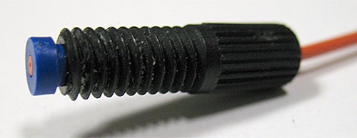
The flow cell will include opaque connectors and tubing that are not appropriate for chromatography. A second set of black PEEK connectors and 1/16" chromatography tubing should also be provided and these should be used (figure 1). In a standard chromatography setup, the eluent will flow from a reservoir through a pump, an autosampler, a column, and finally one or two detectors before flowing to waste. The eluent generally travels through 1/16" tubing after the pump. The black headless PEEK nut should be pushed onto the 1/16" inch tubing. Then the blue or clear flat bottom compression fitting provided should be pushed so they are flush with the end of the tube and securely in place (figure 1).
|
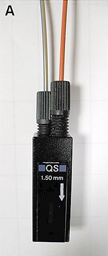
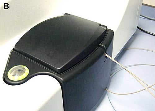
The outlet from the last detector on the customer's equipment (the tube that was flowing to the waste) should be connected to the inlet on the flow cell and then from the outlet of the flow cell to the waste (figure 2). The inlet is in line with an arrow (figure 2A). The lid should be closed without putting too much tension on the tubing (figure 2B).
|
|
Adding the Zetasizer Nano on to the end of a customer's chromatography setup should have no effect on the system. The flow cell can be removed from the Zetasizer Nano, leaving it free for batch use, without having to be disconnected from the fluidics unless desired.
Electrical connections - external detectors
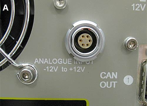
The flow kit should include a cable with a Lemo connection to connect to the back of the Zetasizer Nano (see page 11-19 of the manual for details). The other end should have 4 loose wires labeled 1, 2, 3 and GND (figure 3).
|

|
On the back of each external detector should be connectors to output an analogue signal (e.g. 0-1V). The manuals for the customer's detectors should contain information on these connections. They should help identify the 'signal out' and 'ground' connections. The 'signal out' or '+' connection should be connected to wire 1 on the Lemo cable. The 'ground' or '-' should be connected to wire 4, labelled GND, on the Lemo cable. An extra wire may be required to reach. If a second detector is in use, the procedure can be repeated by connecting 'signal out' to wire 2 and 'ground' to GND, so that both grounds are connected to the same wire - GND - on the Lemo cable. Some detectors are capable of outputting two signals. In this case, the two 'signal out' connections can be connected to wires 1 and 2 respectively, while the grounds will both connect to GND.
The analogue electrical output on the detector must then be setup. This will have the ability to alter the 'absorbance unit full scale' (AUFS). This value should be set so that the sample peak approaches but does not go over the maximum value. For example if the sample generally absorbs 0.3 AU, the AUFS should be set to 0.5. The external detectors need to be set up in the SOP settings. To calculate the gain in the DTS software, the voltage output is divided by the AUFS. In the example above the 1 V output is divided by the 0.5 AUFS to give the gain of 2 for the DTS software.
The delay volume can be calculated after a run has been performed. To do this, right click on the flow record in the records view and choose edit result. Right click on the axis currently showing 'Z-Average Mean' and change it to the external detector. In the 'traces' tab enter the delay to match the peaks in the two chromatograms or using the mouse, drag the external detector trace until it is in line with the intensity trace.
If a voltage other than zero is output when there is no sample present, an offset can be set in the SOP settings to zero the external detector reading.
Many chromatography systems include an autosampler to enable multiple injections to be performed without the need for an operator to be present e.g. overnight. In order to synchronise the actions of the equipment used in this process, most chromatography equipment sends an electrical signal between injectors/pumps/detectors. The Zetasizer Nano can recognise this signal in order to start a run automatically and to synchronise the start of a chromatography run with the start of a flow measurement.
The connector that sends the start signal can be identified by looking at the back of the customer's autoinjector and pump and in the manual. This will be labelled 'inject start' or 'start signal' or 'trigger signal' or similar. The '+' or 'signal' socket is connected to wire 3 on the Lemo cable and the '-' or 'ground' to wire 4, labelled GND, on the cable. To use the start signal in the DTS software, the 'start monitor' macro is required. This is provided on the installation CD in the folder \Extras\Flow Mode\Macros. Runs must be set up using the SOP Player. An SOP with the correct settings for the sample should be created and the Zetasizer Nano should already be at the correct temperature.
A playlist should be created using the SOP Player. The simplest playlist will include the start monitor macro followed by an appropriate flow SOP. When the playlist is started the live display should show that the start monitor is running in the 'SOP Player' tab. A run is started using the customer's chromatography system. When the sample is injected, the DTS software should register the trigger signal and automatically move on to the selected SOP. This process can be set to run as many times as required but it is important to note that the SOP in the DTS software must be finished and the start monitor macro running before the next sample is injected so that the signal is not missed (figure 4).

|
Alternatively: If this does not work - First, the connections should be checked to see that they are all correct. The process should be tried a couple of times to be sure there is no response. In some cases, the injection signal is just a contact closure and no charge is actually sent down the cable so it is not registered. To rectify this, a charge may need to be provided. This can be done in 2 ways. Firstly, a battery can be wired in to provide the charge, although this is not the preferred option. The second and preferred option is to look at the back of the detectors. It is quite likely that there will be a connection on the back of the UV detector to receive an 'inject start' signal. The manuals should help to identify this. This socket can also be connected to the autoinjector using a separate cable, as well as the cable leading to the Zetasizer Nano. This will provide the charge so that when the injection occurs and the contact is closed, a signal will be received.
Electronic connections - ADC monitor
The ADC monitor macros can be used to assess the electrical connections and the signals between them. A separate macro is available for each channel on the analogue inputs (1 & 2 being the eternal detectors; 3 being the start signal) independently of running an actual measurement.
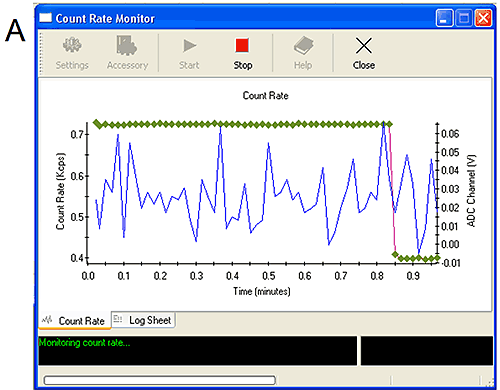
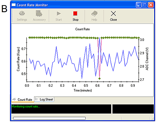
The ADC monitors can be started from the tools menu. They show simply the live count rate from the Zetasizer and the voltage received from the external input (Figure 5). Manipulating the connections themselves or altering the settings on the external detectors should affect the voltage received by the ADC monitor and confirm that the correct signal is being monitored.
Simulating an injection on the autosampler or injecting a sample should give a signal on the channel 3 monitor again confirming that this connection is functioning properly.
Figure 5A shows the ADC monitor for channel 1. Altering the settings on the detector has caused a change in the signal confirming the appropriate connection. Figure 5B shows the ADC monitor for channel 3. When the sample was injected a 0.3 V drop was measured confirming the connection. Two start monitor macros are available. The first (start monitor) will only respond to a 1 V change in measured voltage while the second (sensitive start monitor 0.1 V) will respond to a 0.1 V change in measured voltage. It is recommended to use the sensitive start monitor only when necessary to avoid measurements starting early due to noise in the signal.
|
|
The AKTA chromatography system is in common usage throughout the life sciences market. The connections on this system are not standard but can still be connected to the Zetasizer Nano.
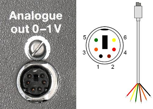
The analogue out signal comes from a 6-pin mini DIN socket located at the back of the instrument (figure 6) labelled 'Analogue out 0-1V'. This contains analogue outputs and grounds for UV, conductivity and pH depending on the configuration of the instrument. A cable may have been provided with the AKTA system but may also need to be provided by installing engineer/technical specialist. This will have an appropriate 6-pin mini DIN plug at one end and loose internal wires at the other. The black wire (1) corresponds to the UV 'signal out' and the brown wire (2) corresponds to the appropriate ground. Connecting these two to the wires on the Lemo cable (1 and GND respectively) should provide the analogue UV signal.
|
The gain and signal scale must be modified on the instrument itself. Using the wheel and buttons on the front of the Monitor UPC-900 these settings can be changed. Using the wheel select - Set Parameters: UV: Set UV Analogue Out: Set UV range. An appropriate AUFS setting should be chosen as described above and the appropriate 'gain' value entered into the DTS software. If these controls are locked, they can be released in the Unicorn software controlling the AKTA system. Choose the system control application, click 'system', 'settings', then 'specials'. Choose the 'keyboard mode' and change the setting to 'open'.
When the signal becomes negative, the analogue output from the AKTA is reset to 1 V to show the decrease. To avoid this, an offset can be set into the instrument such that the output signal is 2% (0.02 V) above 0. This is done on the Monitor UPC-900. Using the wheel select - Set Parameters: UV: Set UV Analogue Out: Set UV zero level. This can be countered in the DTS software by setting the offset to -0.02 in the external detector settings. It is useful to include this step to avoid the analogue signal jumping to 1V at random intervals throughout the run.
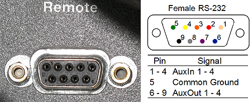
The start signal can be set to come from the 'remote' socket on the back of the AKTA instrument (figure 7). This is an RS-232 type socket. Pins 6-9 correspond to 'AuxOut' signals and pin 5 is a universal ground signal.
|
A new cable should be made by connecting wires to pins 5 and 6 on a new RS-232 plug, or an existing cable can be cut and the wires connecting to pins 5 and 6 identified (green and blue, respectively). The cable is plugged into the socket on the back of the AKTA instrument. The wire connected to pin 5 is connected to wire 3 on the Lemo cable from the Nano and the wire connected to pin 6 to GND on the Lemo cable.
The Unicorn software controlling the customer's AKTA system is required to control the signal. Click on 'manual' - 'pump' in the menu of the 'system control' application. The menu should include a number of options including AuxOut 1 to 4. If the wire has been correctly connected, then AuxOut1 should act as the start signal. If the aux signals are not present, they need to be activated in the system settings.
Go to the 'Unicorn manager' application. Click on 'admin' - 'system setup'. Click on the diagram representing the chromatography system and click 'edit' then on 'components'. Check the box next to 'Auxiliary equipment' and click 'Ok'. The AuxOut signals should now be available in the 'manual' - 'pump' options and in the method editor.
The playlist created earlier should be run using the SOP player. In the AKTA Unicorn software - system control application - manual - pump - AuxOut 1 option, change the signal from 0 to 1 (or 1 to 0) and click 'execute'. This should trigger the Zetasizer Nano to move on from the start monitor to the SOP. When writing a chromatography method in the unicorn software, the inject command must be accompanied by the AuxOut1 switch from 0 to 1 (or 1 to 0) so that a trigger signal is sent to the Zetasizer Nano. Thus, when the sample is injected, the signal is sent at the same time to the Zetasizer to start the measurement.
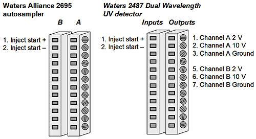
The following connections are made between the Zetasizer Nano, the Waters Alliance separation unit and the Waters 2487 Dual Wavelength Absorbance Detector.
The detector measures at two wavelengths (A & B) so these can be set as external detectors 1 and 2 respectively. The analogue outputs on this device are screw fittings. Wire 1 from the Lemo cable is connected to socket B1 and GND from the Lemo cable to socket B3 for the wavelength A. Wire 2 from the Lemo cable is connected to socket B5 and GND from the Lemo cable to socket B7 for the wavelength B. An extra cable may be needed to connect GND from the Lemo cable to both sockets. These detectors output a 2 Volt signal. The detectors allow the AUFS of the output to be modified. The AUFS and Gain are set according the instructions above.
The start signal from the separations module is connected to the Zetasizer Nano. The 2695 module has 2 connections for an inject start output labelled B1 and B2. However, this is simply a contact closure, so when connected, does not provide a charge signal to initiate the measurement by the Zetasizer Nano. The 2487 detector also has connections for an inject start signal labelled (A1 and A2). No trigger is associated with these connections but a current is sent by them. The following setup enables the contact closure from the 2695 module to be used with the current from the 2487 Detector and the Zetasizer Nano. Wire 3 of the Lemo cable is connected to socket A1 on the 2487 detector. A second wire is connected from this socket to socket B1 on the 2695 module. The final connection is GND of the Lemo cable to socket B2 on the 2695 module. Thus, when the contact is closed between B1 and B2 on the 2695 module, the signal from the 2487 detector should be registered by the Zetasizer Nano initiating the run.
These HPLC instruments are the white stackable systems. The individual units communicate with each other using CAN connectors that look like Ethernet connectors.
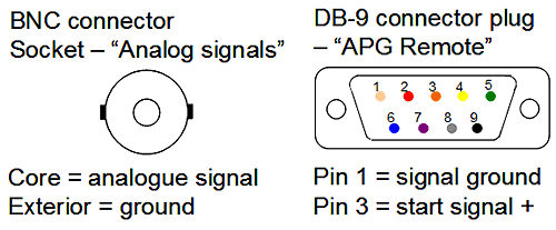
At the back of the detector a BNC connector is used to output an analogue signal. The outside is the ground. This should be connected to GND on the Lemo cable and the core of the BNC connector to pin 1 or 2 on the Lemo cable as desired. Using the software, the BNC analogue output can be configured to send either the VWD or the dRI signal for the RI detector.
|
The pump has a DB-9 connector at the back labelled REMOTE. Pin 1 connects to Lemo wire 4, labelled GND, while pin 3 from the APG remote goes to the wire 3 of the Lemo cable. A cable will need to be prepared connecting pins 1 and 3 to wires for connection to the Lemo cable. Alternatively, an existing cable can be cut and the appropriate wires identified. No configuration of the hardware is needed so when a playlist is setup in the DTS software, as described above, the Zetasizer Nano should detect a signal from the instrument and begin running the measurement when the sample is injected. Figure 9 shows the two relevant sockets.
|
ÄKTA is a trademark of GE. Healthcare Bio-Sciences AB.
Waters Alliance is a registered trademark of Waters Corporation.
Agilent, HP and 1050, 1100, 1200 are trademarks of Agilent Technologies Corp.
Malvern Zetasizer Nano is a trademark of Malvern Instruments.
All other trademarks are acknowledged.