The data and method described in this application note resulted from a common work of Dr. Stefan Seidlmayer (TU München) and Armin Kriele (Helmholtz Zentrum Geesthacht) from the Heinz Maier-Leibnitz Zentrum, MLZ in Garching (Germany). The MLZ is a neutron research facility open for user experiments in science and industrial application.
Lithium-ion batteries have become increasingly important in key technologies of our day-to-day lives. Especially the long-term performance of batteries is crucial for their applications in new markets such as energy storage in electric vehicles or even large-scale electric storage devices combined with photovoltaic energy sources.
For these large-scale applications a key requirement is very good long-term and cycling performance. Improvement of this performance requires studying ongoing aging processes inside batteries continuously and without the need to destroy and disassemble them prior to the analysis (in operando analysis). This is especially important as many cell components deteriorate due to the disassembly process or when exposed to air or moisture.
Often X-ray synchrotron or neutron radiation based methods are used in this context [1-4]. The strengths of these methods are their high penetration capabilities and their ability to use specially encapsulated samples or even industrially manufactured samples directly. Nevertheless, a drawback of these methods is the restricted access as they are only available at large-scale research facilities and obtaining the required beam time is typically a longer process.
While neutron scattering is very sensitive to light elements such as Li, X-ray powder diffraction provides a much higher resolution of the cell parameters and therefore both are complementary techniques. A large variety of experimental cells for XRD studies has been developed such as specially adapted coin cell type batteries for reflection geometry. Typically XRD setups of lab diffractometers are based on using copper radiation and rely on using so-called ‘half-cells’, containing only one active electrode while the other electrode is then only a thin foil of lithium metal. Although this is adequate to study the principal transformation mechanism and the corresponding structural changes of the electrode active material via diffraction methods, it is insufficient for studying complex aging processes. These depend heavily on even the smallest changes in cell chemistry and material composition and require monitoring the structural evolutions of both electrodes at the same time. For such aging studies one cannot rely on half-cell studies but has to observe the cells under real operating conditions in their native environment.
The pouch bag cell design offers this possibility. It is easy to manufacture reproducibly. It is versatile enough for experimental changes and offers the possibility to use all standard battery grade materials and components. An industrial prototype can be assembled for the continuous monitoring of cells subjected to different aging procedures. In synchrotron beam lines such pouch cells have already been used successfully [5]. The battery research group headed by Dr. habil. Ralph Gilles (TU München) at the Heinz Maier-Leibnitz Zentrum (MLZ) in Garching (Germany) has adapted and further developed this method in order to use standardized pouch cells for diffraction experiments on a lab XRD instrument like the Empyrean using hard X-ray radiation. This allows investigation of the structural dynamics of fully closed pouch bag type batteries as used as industrial prototype samples during typical aging procedures directly and without any prior dismantling.
Pouch cell batteries can be used in combination with hard X-rays in transmission geometry to perform in situ and in operando studies during charge/discharge cycles and for aging studies. It is then possible to correlate variations in the crystallographic structure of the elements in the cell directly with the amount of Li incorporated in the electrodes. Moreover, the efficiency of the GaliPIX3D detector can considerably improve data quality compared to standard Si- based detectors.
Login or create an account to read more about this case study.
The data and method described in this application note resulted from a common work of Dr. Stefan Seidlmayer (TU München) and Armin Kriele (Helmholtz Zentrum Geesthacht) from the Heinz Maier-Leibnitz Zentrum, MLZ in Garching (Germany). The MLZ is a neutron research facility open for user experiments in science and industrial application.
Lithium-ion batteries have become increasingly important in key technologies of our day-to-day lives. Especially the long-term performance of batteries is crucial for their applications in new markets such as energy storage in electric vehicles or even large-scale electric storage devices combined with photovoltaic energy sources.
For these large-scale applications a key requirement is very good long-term and cycling performance. Improvement of this performance requires studying ongoing aging processes inside batteries continuously and without the need to destroy and disassemble them prior to the analysis (in operando analysis). This is especially important as many cell components deteriorate due to the disassembly process or when exposed to air or moisture.
Often X-ray synchrotron or neutron radiation based methods are used in this context [1-4]. The strengths of these methods are their high penetration capabilities and their ability to use specially encapsulated samples or even industrially manufactured samples directly. Nevertheless, a drawback of these methods is the restricted access as they are only available at large-scale research facilities and obtaining the required beam time is typically a longer process.
While neutron scattering is very sensitive to light elements such as Li, X-ray powder diffraction provides a much higher resolution of the cell parameters and therefore both are complementary techniques. A large variety of experimental cells for XRD studies has been developed such as specially adapted coin cell type batteries for reflection geometry. Typically XRD setups of lab diffractometers are based on using copper radiation and rely on using so-called ‘half-cells’, containing only one active electrode while the other electrode is then only a thin foil of lithium metal. Although this is adequate to study the principal transformation mechanism and the corresponding structural changes of the electrode active material via diffraction methods, it is insufficient for studying complex aging processes. These depend heavily on even the smallest changes in cell chemistry and material composition and require monitoring the structural evolutions of both electrodes at the same time. For such aging studies one cannot rely on half-cell studies but has to observe the cells under real operating conditions in their native environment.
The pouch bag cell design offers this possibility. It is easy to manufacture reproducibly. It is versatile enough for experimental changes and offers the possibility to use all standard battery grade materials and components. An industrial prototype can be assembled for the continuous monitoring of cells subjected to different aging procedures. In synchrotron beam lines such pouch cells have already been used successfully [5]. The battery research group headed by Dr. habil. Ralph Gilles (TU München) at the Heinz Maier-Leibnitz Zentrum (MLZ) in Garching (Germany) has adapted and further developed this method in order to use standardized pouch cells for diffraction experiments on a lab XRD instrument like the Empyrean using hard X-ray radiation. This allows investigation of the structural dynamics of fully closed pouch bag type batteries as used as industrial prototype samples during typical aging procedures directly and without any prior dismantling.
Pouch cell batteries can be used in combination with hard X-rays in transmission geometry to perform in situ and in operando studies during charge/discharge cycles and for aging studies. It is then possible to correlate variations in the crystallographic structure of the elements in the cell directly with the amount of Li incorporated in the electrodes. Moreover, the efficiency of the GaliPIX3D detector can considerably improve data quality compared to standard Si- based detectors.
The first set of measurements was performed at the Heinz Maier-Leibnitz Zentrum (MLZ) in Garching (Germany), where a customized transmission setup was used for the in situ measurements, using an Empyrean diffractometer with an X’Celerator detector. The second set of measurements was performed at Malvern Panalytical headquarters in Almelo (the Netherlands), and it includes a comparison of the results obtained with an X’Celerator and the GaliPIX3D detector. Mo radiation was used for both measurements, in combination with a focusing beam X-ray mirror. Photographs of the setups used and the pouch cell are presented in Figure 1.
The cell was cycled twice between discharged and charged states following a sequential CCCV (constant current – constant voltage) procedure. First the cell is charged incrementally in ten steps with a C/10 rate and 2 h stops in the current flow. Then the cell is charged further until it reaches a certain cut-off voltage potential and the current flow drops below the cut-off threshold. The cell potential and current flow during the procedure are shown in Figure 2. The in situ XRD measurements were performed continuously over several days, and consisted of two complete charge/ discharge cycles of the battery cell (see Figure 3). Powder diffraction scans were collected continuously; each scan in the range 5° to 55° 2theta with a measurement time for each scan of 16 minutes 44 seconds. Subsequently, scans measured during the ramping of the current were discarded, and the scans performed at constant zero current value were analyzed. A script was written in HighScore Plus (version 4.1 [6]) to automatically merge all the scans measured at the same conditions.
Figure 1. Top to bottom: typical pouch bag battery after assembly; setup used at the Heinz Maier-Leibnitz Zentrum (MLZ) in Garching for in situ measurements; measurement setup used for testing GaliPIX3D performance
Samples were measured with the following parameters:
| Instrument | Diffractometer |
|---|---|
| Radiation | Mo Kα |
| Incident beam optics | Focusing mirror with ¼ Ta divergence slit, ¼ Ta anti-scatter slit, 0.02 rad Soller slit, 10 mm |
| Sample stage | 3-axes cradle in combination with customer-designed sample holder |
| Diffracted beam optics | Anti-scatter slit, 0.02 rad Soller slits |
| Detector | X’Celerator and GaliPIX3D |
| Scan parameters | 5° - 55° 2θ scans, 16 min scan time
|
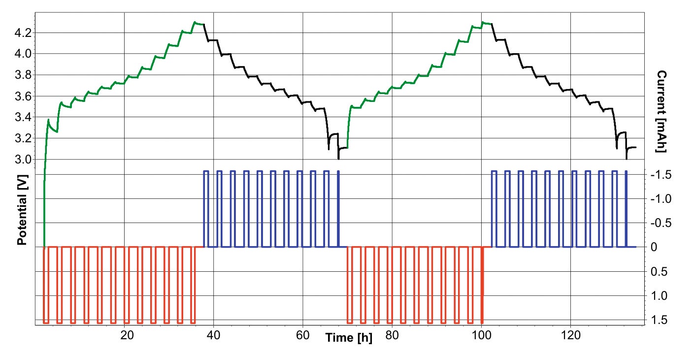
Figure 2. Cell potential and current during XRD measurements. In green/black the potential during charge and discharge respectively (left axis). In red/blue the current (right axis)
The energy storage in a Li-ion battery is achieved by forcing Lithium batteries used in the measurements were Li ions to move from the cathode active material to the assembled in the so-called pouch bag format. In this anode active material by applying an electrochemical force assembly type, the electrodes of the battery are protected (Figure 3). Inside a thin polymer composite hull (pouch). This pouch is a complex polymer/metal assembly of an aluminium foil sandwiched between polymer layers The overall thickness of such a pouch bag is ~100 µm. Figure 4 shows a schematic view of such a cell.
The electrodes were prepared by coating thin metal current collector foils with dispersions of active materials in NMP (N-methyl-2-pyrrolidone). The dry thickness of the coatings was ~60 µm. For anodes, a 10 µm Cu foil was coated with artificial graphite and PVDF-binder.
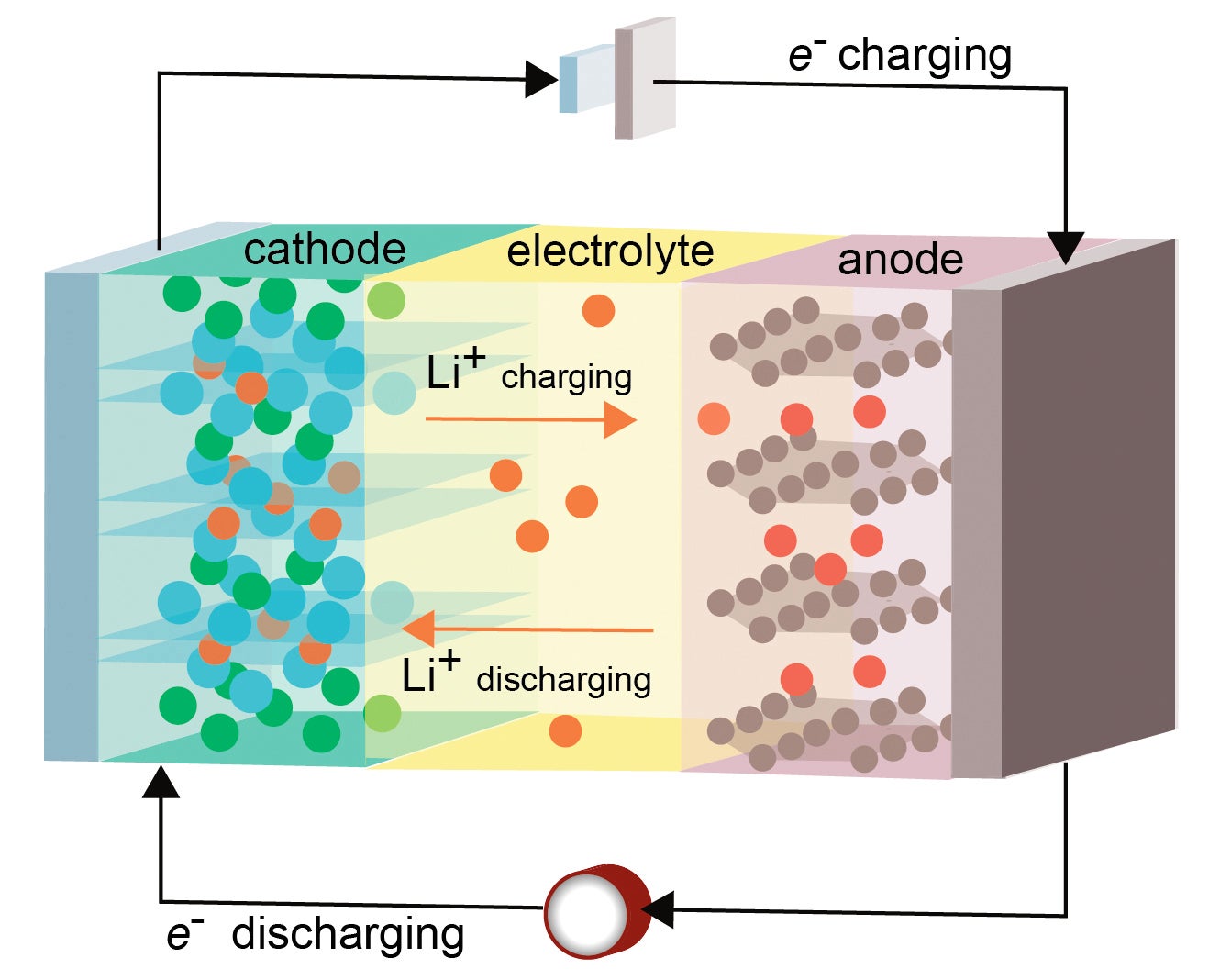
Figure 3. Schematic view of a lithium-ion battery
During charging an external electrical power source applies an over-voltage (a higher voltage than the current to pass in the reverse direction. The lithium ions then migrate from the cathode to the anode, where they as intercalation.
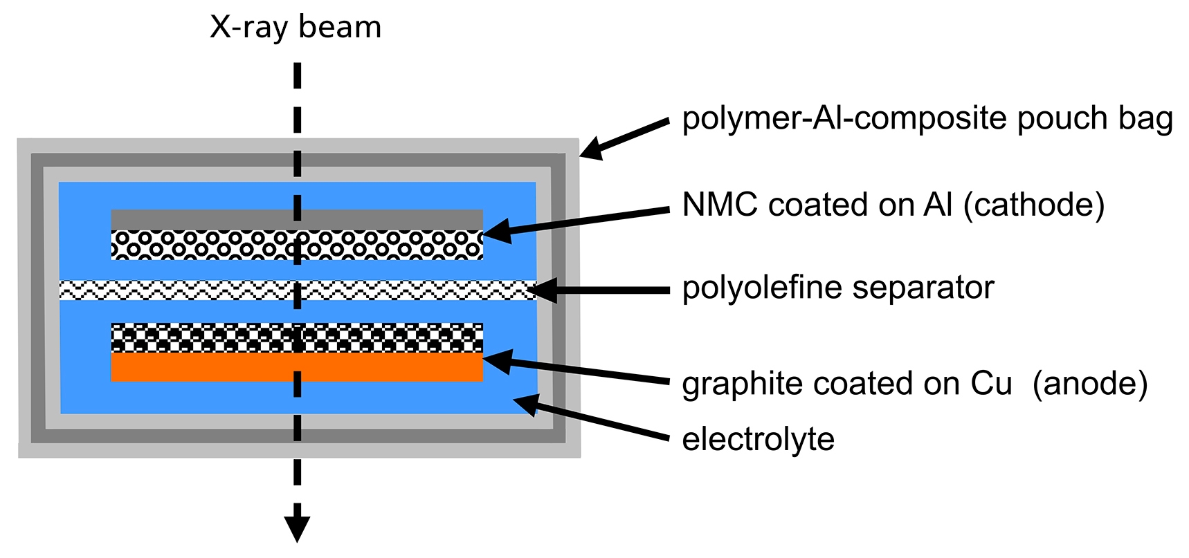
Figure 4. Schematic view of a pouch bag cell
Automatic Rietveld and Pawley mixed fits were performed with HighScore Plus on every scan, to obtain the cell parameters for the LiNMC and the graphite phases. An example of the fit is shown in Figure 6. The cell parameters obtained during the fit were automatically exported to a spreadsheet file, and the results can be found in Figure 5.
From the automated fits changes in the lattice parameters can be observed, which relate directly to the structural evolution of the electrode materials during the intercalation/ deintercalation process. Most striking feature is the different behavior of the a- and c-axis of the LiNMC cathode. During the charge process, which corresponds to removal of lithium ions from the structure of the cathode, the a cell parameter first shows a decrease followed by a shorter region where it is nearly constant. On the other hand the c-axis shows first a strong increase and then switches to a decrease just before the cell is fully charged. Both these trends are reversible upon discharge of the battery.
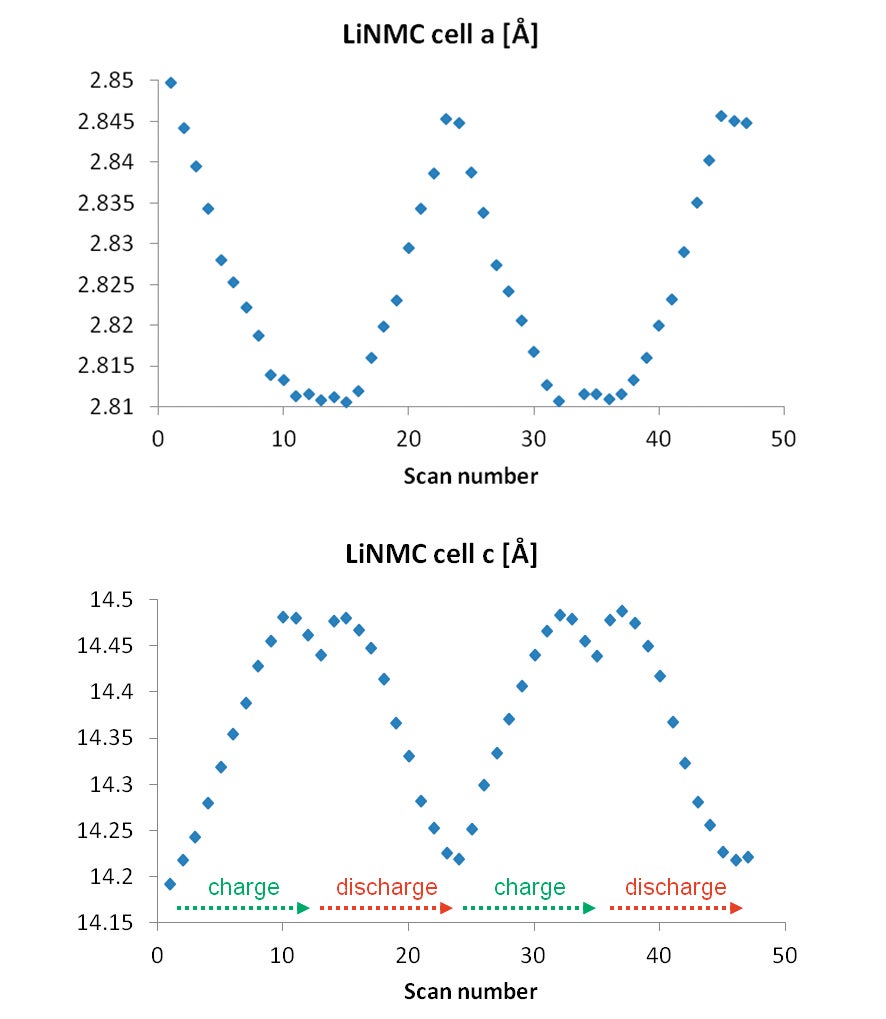
Figure 5. Fitted LiNMC lattice parameters
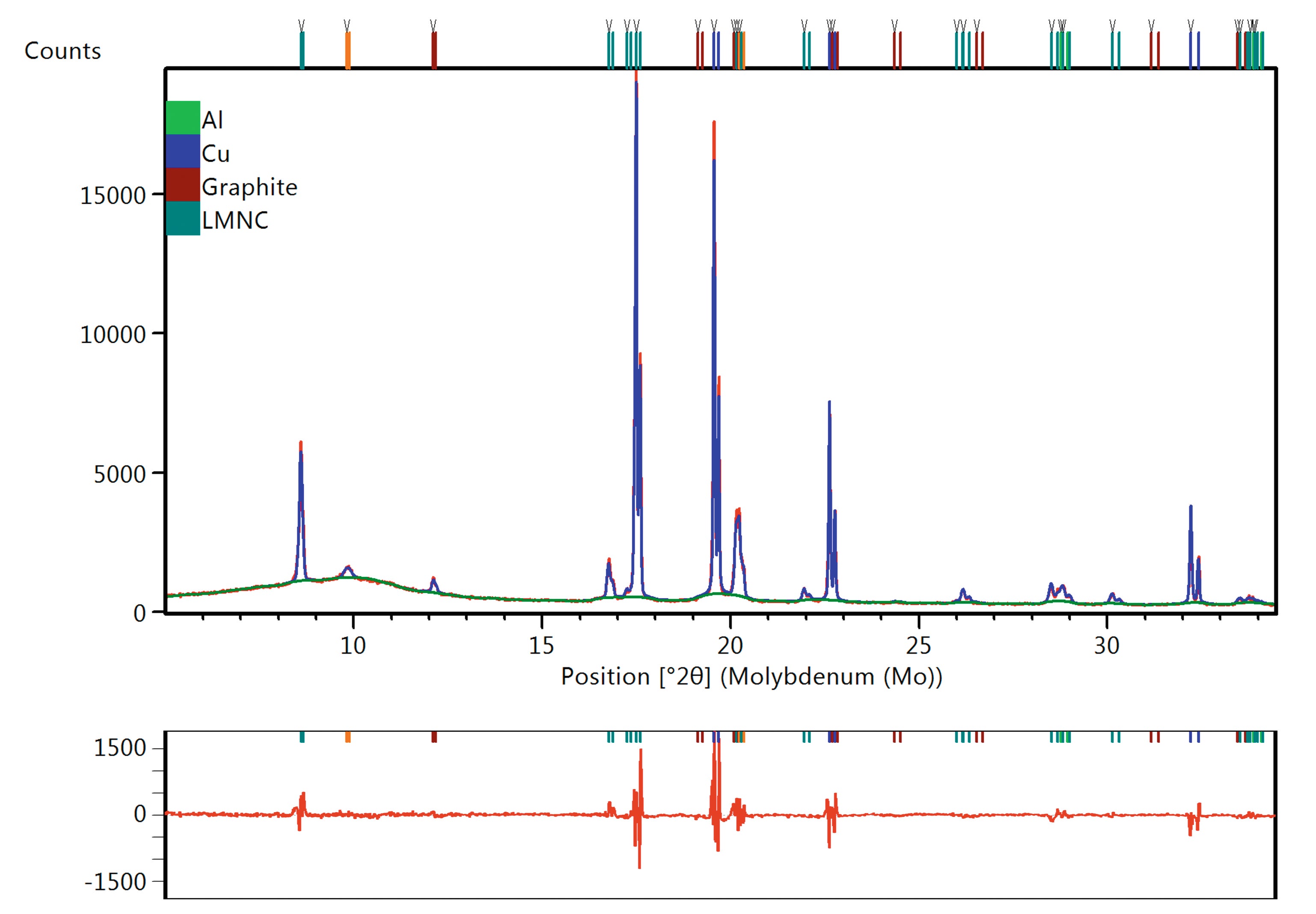
Figure 6. Example of the data including the different phases, the automatic fit and the difference plot in the lower panel
The structure of the layered transition metal oxide LiNMC is shown in Figure 7.
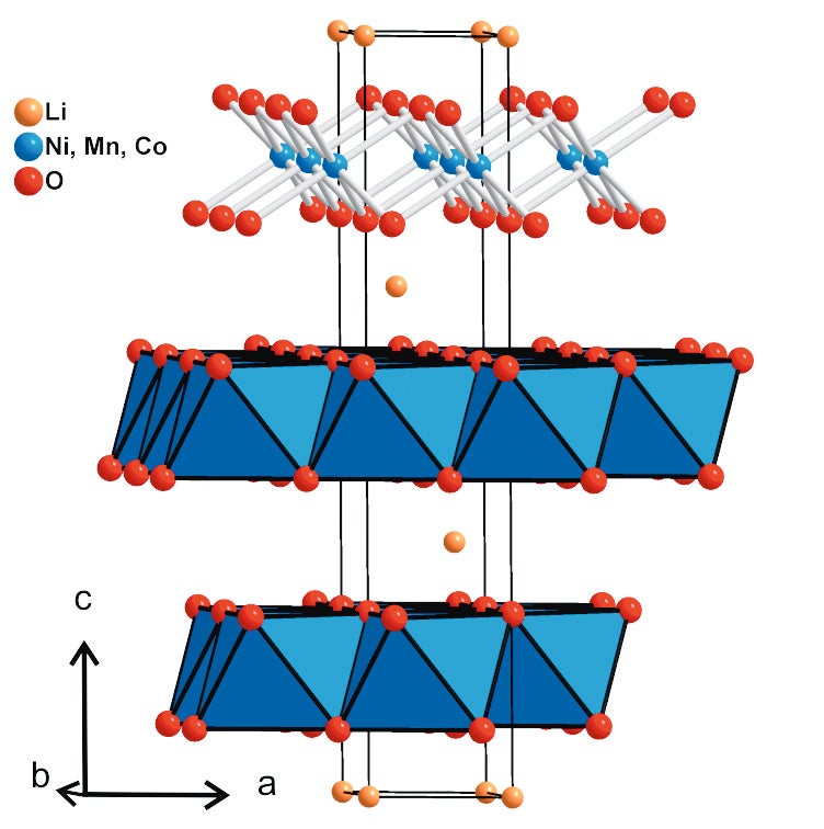
Figure 7. Projection of the crystal structure of the LiNMC cathode along b
The transition metal atoms are arranged in layers of edge- sharing MO6-octahedra. These layers are stacked along the c-axis with an ABC-packing sequence. The lithium atoms are inserted in the interlayer space between the MO6-layers and are octahedrally coordinated by oxygen atoms. These observations can be rationalized considering the structural features. During charging the lithium atoms leave the structure and an increase in the oxygen-oxygen electrostatic repulsion expands the lattice along the c-axis. At the same time the average oxidation state of the transition metal atoms is successively increasing while Li+ ions are leaving the structure to maintain the overall charge balance. This leads to a stronger ionic interaction between metal and oxygen atoms leading to a shortening of the M-O bonds which are lying within the a-b-plane and thus resulting in a decrease of the a lattice parameter.
When the sample mass and thus the absolute number of moles of active LiNMC material in the cell is known, one can also calculate the amount of x(Li) in the formula as every transferred electron equals one lithium atom. This means that for the charge/discharge process one can also write the formula of LiNMC as Li1-xNi0.33Mn0.33Co0.33O2. It is interesting to plot either the lattice parameters or the parameter ratio c/a versus the calculated amount of x(Li) in Li1-xNMC as shown in Figure 8.
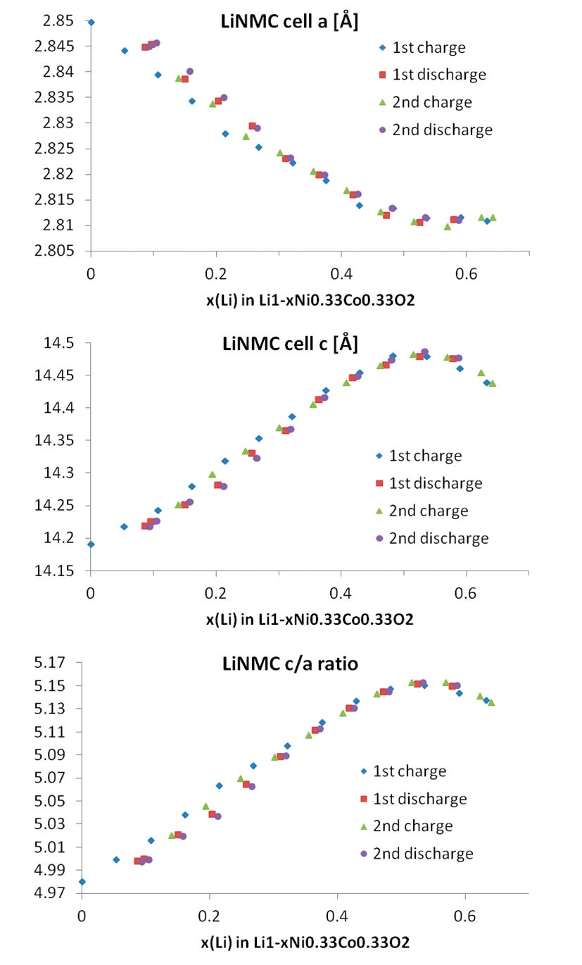
Figure 8. Cell parameters obtained for the LiNMC and graphite phases, as a function of the Li content
This correlation shows that there is some hysteresis between the first and successive charge/discharge cycles in regard to the lattice parameters. This effect is called irreversible capacity loss (ICL). It is a result of the very slow uptake of lithium ions upon re-insertion into the host Li1-xNMC structure when reaching x-values close to 1. By measuring the linear correlation between the lattice parameter ratio c/a and the lithium content x(Li) during the 1st and 2nd cycle of the cell with in situ XRD it is also possible to obtain a value for the amount of active lithium in the cathode. It is important to highlight that this value can then be compared to the electrically observable capacity. Deviations of these two values from each other give valuable insights for the understanding of aging processes in lithium-ion batteries [7]. By using the isolines plot available in HighScore, it is also possible to observe the variation of the cell parameters directly by following the shifting of the Bragg peaks for LiNMC as well as for graphite, see Figure 9.

Figure 9. Variation in the XRPD data during two full charge and discharge cycles. The peaks at about 8.5° and 17° 2theta belong to the LiNMC phase, (003) and (101) reflections respectively. The peak at about 12° 2theta is the (002) reflection of graphite.
With the transmission geometry setup and the pouch bag cells in the in situ XRD setup, it is not only possible to follow the structural changes due to the deintercalation of lithium from LiNMC on the cathode. Simultaneously the changes due to the lithium intercalation into the graphite host lattice on the anode side of the cells can be followed (see Figure 10).
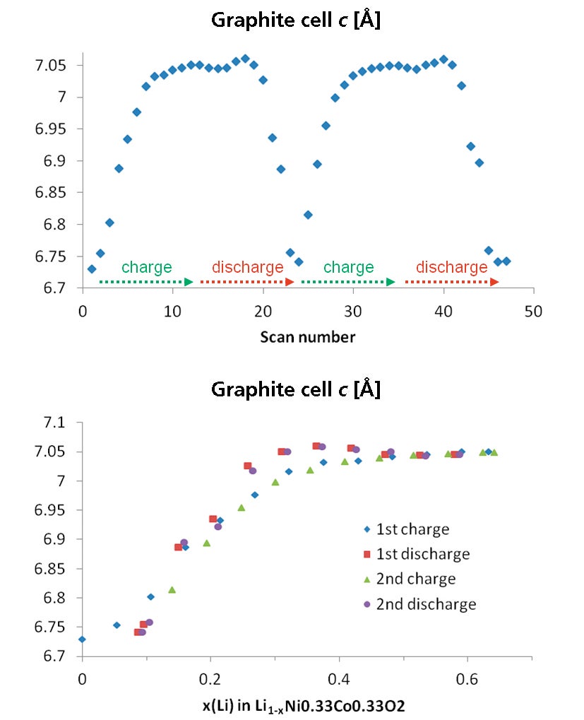
Figure 10. Graphite cell parameters as a function of scan number (left) and lithium content (right)
The detailed structural dynamics involved in the transformation of the structure of pure graphite into the structure of the fully intercalated graphite, LiC6, can also be observed. The graphite structure consists of graphene layers packed along the c-axis. Following the lattice parameters (Figure 10) starting with a graphite basic structure, first a lattice expansion along the c-axis can be observed. This is explained with the insertion of the lithium atoms into the interlayer space of the graphite host structure resulting in an expansion along the c-axis to accommodate the additional lithium ions in the structure.
The GaliPIX3D, a 1D/2D detector with a high-quality CdTe sensor, is the ideal detector for this application. Over the X'Celerator used in this study it offers a ~five times higher intensity which can be used to collect data with higher resolution (by narrowing slits) or in the shortest possible time frame. The GaliPIX3D can also be used for the analysis of amorphous or highly disordered materials using the pair distribution function (PDF) method and/or transmission X-ray imaging and computed tomography (CT).
Figure 11 shows the performance difference between the two detectors on the same pouch cell. It clearly demonstrates the benefit of using GaliPIX3D for in operando measurements on complete electrochemical cells in the transmission geometry.
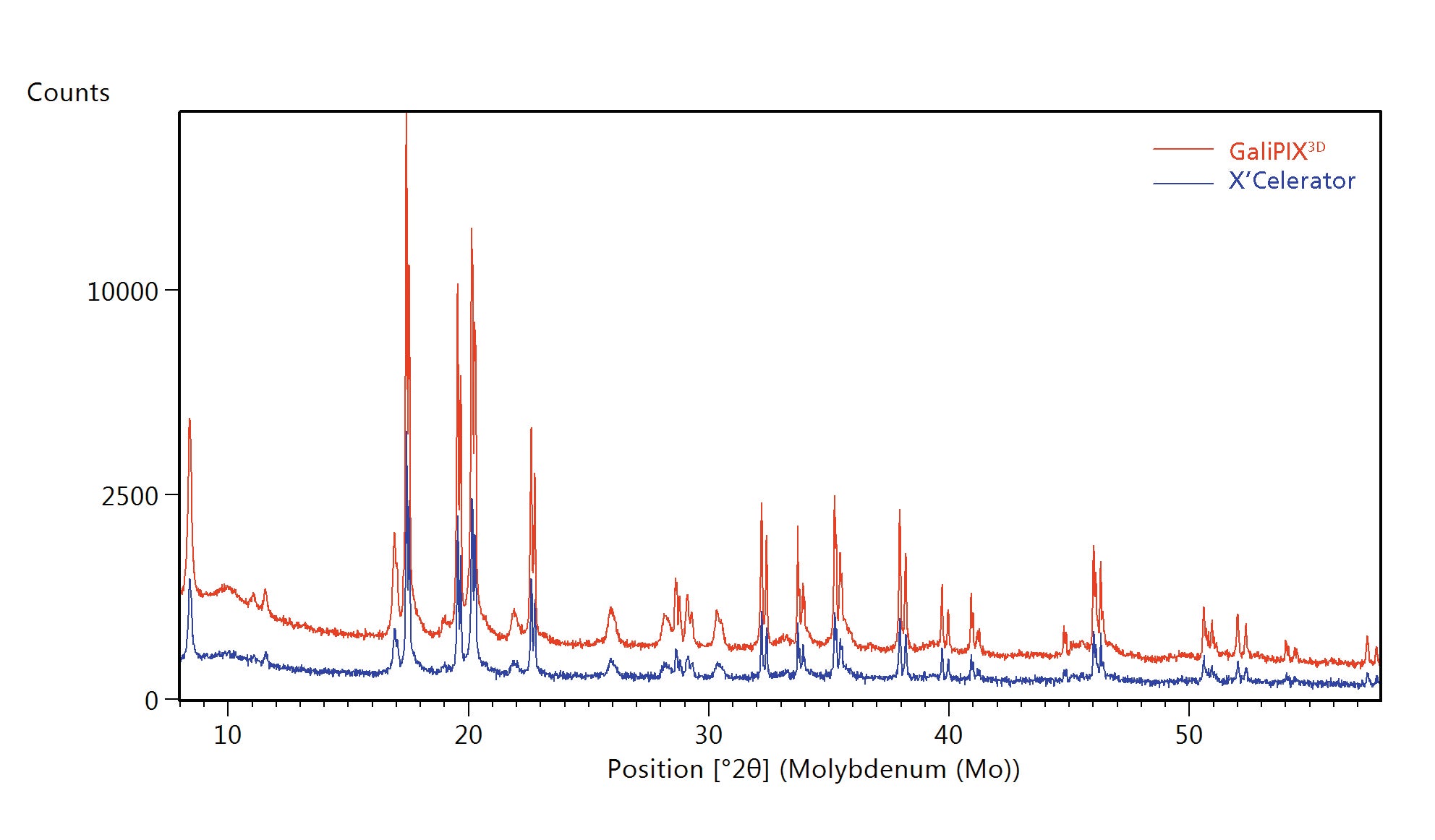
Figure 11. Comparison of data measured using the same setup and total scan time with GaliPIX3D data (red) and X’Celerator data (blue)
Pouch cells batteries can be measured in situ and in operando with hard X-rays in transmission geometry as a standalone method or as a complementary technique to neutron diffraction. Information about the cell parameters of anode and cathode have been obtained using the HighScore Plus software. GaliPIX3D is the ideal detector for this kind of study, thanks to its extremely high efficiency in detecting hard X-rays.
[1] V. Zinth, S. Seidlmayer, N. Zanon, G. Crugnola, M. Schulz, R. Gilles, and M. Hofmann, Journal of The Electrochemical Society, 162 (3), A384-A391 (2015).
[2] M. Morcrette, Y. Chabre, G. Vaughan, G. Amatucci, J. B. Leriche, S. Patoux, C. Masquelier, and J. M. Tarascon, Electrochimica Acta, 47 (19), 3137-3149 (2002).
[3] S. Seidlmayer, J. Hattendorff, I. Buchberger, L. Karge, H. A. Gasteiger, and R. Gilles, Journal of The Electrochemical Society, 162 (2), A3116-A3125 (2015).
[4] C. Kortenbruck, R. Gilles, A. Senyshyn, V. Zinth, M. Hofmann, C. von Lüders, O. Dolotko, M. Mühlbauer, S. Seidlmayer, and N. Paul, Neutron News, 26 (1), 29-32 (2015).
[5] K. W. Nam, W. S. Yoon, H. Shin, K. Y. Chung, S. Choi, and X. Q. Yang, Journal of Power Sources, 192 (2), 652-659 (2009).
[6] T. Degen, M. Sadki, E. Bron, U. König and G. Nénert. Powder Diffraction, 29, S13-S18, (2014)
[7] I. Buchberger, S. Seidlmayer, A. Pokharel, M. Piana, J. Hattendorff, P. Kudejova, R. Gilles, and H. A. Gasteiger, Jou