Philippe Dumas[1], Eric Ennifar[1], Guillaume Bec[1], Angel Piñeiro[2,3], Juan Sabn[2], Eva Muñoz[2], Javier Rial[2] -
[1] Biophysics & Structural Biology team, IBMC, UPR9002 du CNRS, Université de Strasbourg.
[2] AFFINImeter Scientific & Development team, Software 4 Science Developments, S. L. Ed. Emprendia, Campus Vida, Santiago de Compostela, A Coruña 15782, Spain.
[3] Dept of Applied Physics, Fac. of Physics, University of Santiago de Compostela, Campus Vida, Santiago de Compostela, A Coruña 15782, Spain. Corresponding author: p.dumas@unistra.fr

|
It is commonly thought that ITC is a typical thermodynamic technique that is not really suited to extract kinetic information. It is thus commonplace to oppose ITC to SPR since the latter is a kinetic technique par excellence. However, this is at best an oversimplification since ITC is based upon kinetic measurements. Indeed, the raw signal measured in any ITC experiment is a heat power (in µJ s-1 or µcal s-1), that is essentially the rate of heat production, and not the heat itself evolved in a reaction. Obviously, this rate of heat production is directly related to the kinetics of the reaction taking place in the measurement cell, which is the reason why a microcalorimeter is potentially much more than merely a ‘heat-meter’. This is in line with the common observation that there are systems showing after each injection a quick return to baseline, that is a quick equilibration time, and others, on the contrary, showing slow, and even very slow, return to baseline. It should not come as a surprise, therefore, that ITC has already been used to derive kinetic information. Many readers, however, will probably be surprised to learn that the first “compensation-mode” calorimeter (the ancestor of the MicroCal VP-ITC and MicroCal ITC200 instruments) was devised in 1924 and used first to measure the heat power produced by flies [1, 2]. Therefore, the first “compensation-mode” calorimeter was used for what we now call a kinITC experiment.
In chemistry and physical chemistry, the link between the measured heat-power and the kinetics of the reaction has long been the subject of theoretical investigations [3-5]. However, the possibilities of the instruments of the time, particularly due to their large sample volumes of several ml and their long response times, were quite limited and the measurements were exclusively limited to slow, and sometimes very slow, reactions [6].
In the biological field, therefore, kinetic measurements have mostly been performed in enzymology after the pioneering work by Sturtevant initiated in 1937 (reviewed in [7]). Modern instruments like the MicroCal ITC200 with a 200-µl measurement cell and response times better than 10 s (3.5 s for the MicroCal ITC200 instrument used for this study) provide us with the possibility of addressing more easily biological problems not limited to enzymatic studies. Such response times can be derived from methanol dilution experiments described below. Interestingly, a recent study on slow RNA folding showed that the VP-ITC may also be valuable [8]. It is the goal of this Application note to show how and when can kinetic information be retrieved from ITC power curves. The results shown here were obtained with programs developed with Mathematica from Wolfram Research, which was employed to implement and validate the method. The underlying algorithms were all introduced into AFFINImeter and they are expected to be publicly available by April 2015.
A full account of the complete kinITC method has been given in [9]. Here, we will make a brief summary of it and emphasize on a simplified version that can yield remarkably good results as soon as a classical ITC data analysis has been performed. It has to be stressed that, in [9], we considered applications of kinITC in two different situations, first for a simple one-step kinetic scheme represented by:
A + B ↔ C with parameters kon, koff (1)
and, second, for a two-step kinetic scheme with a binding event followed by a conformational change (‘induced fit’). In the present Application Note, we focus only on one-step kinetic schemes represented by equation (1). Essentially, kinITC is based upon linking the kinetics of the reaction to heat power production in the measurement cell. Elementary kinetic considerations yield:
dC/dt=kon[A]0AB-koffC (2)
where A, B and C are simplified notations for the reduced concentrations [A]/ [A]0, [B]/ [A]0 and [C]/ [A]0, [A]0 being the concentration of the titrand in the measurement cell before any injection of the titrant B. This differential equation is valid at any step of the titration (i.e. for any ‘injection’), but only after compound B has been injected, which ensures that the system ‘is closed’ and that the following conservation equations apply: A + C = constant and B + C = constant. During the injection of a small volume δV of compound B, on the contrary, the variations of A, B and C are also affected by the addition of B and by the resulting dilution (each added volume δV has to displace the same volume δV from the cell), which makes equation (2) insufficient to describe the system. These technical problems are fully addressed in AFFINImeter but they are not essential for the understanding of kinITC and we will thus focus only on the evolution of the system immediately after compound B has been injected.
The link between dC/dt and the heat power signal PS at any time t after injection of compound B is readily obtained as:
PS(t)=VcellΔH[A]0dC/dt (3)
where Vcell is the cell volume (200 µL for the MicroCal ITC200 and 1.4 ml for the VP-ITC). Therefore, when dC/dt is known from integration of equation (2) (see [9]), Ps(t) can be evaluated. Note that Ps(t) is not the measured heat power Pm(t) due to the finite response time (or relaxation time) τITC of the instrument. The link between and is expressed by a classical convolution equation:
Ps(t)=Pm(t)+τITCdPm/dt (4)
This equation, which has been known since 1933 as the Tian equation in the frame of calorimetry (for accessible references, see [3, 10]), is in fact a universal equation describing the influence of a finite response time on any instrument having a linear response. Obviously, the shorter τITC, the less distorted the measured signal. We will consider in the following the limits of kinITC arising from a non-null τITC value. To gain insight into the influence of this important parameter on the shape of the injection curves, see http://www-ibmc.u-strasbg.fr:8080/webMathematica/kinITCdemo/. Importantly, whatever the value of τITC, equation (4) shows that the integration of Pm(t) and Ps(t) leads to the same total heat, but only if one has left enough time between injections for the signal to return to equilibrium (see below).
Experimentally, τITC can be obtained by fitting with Pm(t)=Pmaxexp(-t/τITC) the decaying response of the instrument to a very fast thermal excitation like that following the quick injection of diluted methanol (1µl injections of 1-3% v/v MeOH). By ‘decaying response’ we mean the response after the end of the short transient signal due to the excitation itself. For the MicroCal ITC200, this allows to obtain τITC≈3.5s. Note that some variability may exist from instrument to instrument. Finally, it should be mentioned that, rigorously, a single relaxation time may not be sufficient to describe fully the response of an instrument [4, 5, 10]. We do not have to consider these refinements for the present purpose.
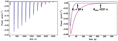
Quite often, when examining the successive injections, one easily discerns a significant variation of the time θ needed to return to baseline or, in other words, of the equilibration time. In particular, the injection corresponding to, or close to, mid-titration (i.e. [A] = [B] when there is one single binding site) shows the slowest equilibration time. This is illustrated with calculated data in Fig. 1. Such a feature is a clear mark of the existence of a kinetic signal. Intuitively, the explanation is that, close to mid-titration, both the concentrations of A and B are low (and even very low if the affinity is high), which slows down the kinetics of a 2nd order reaction according to equation (2). As a consequence, it is critical to leave enough time for recording in full these ‘mid-titration injections’ with longer equilibration times.

|
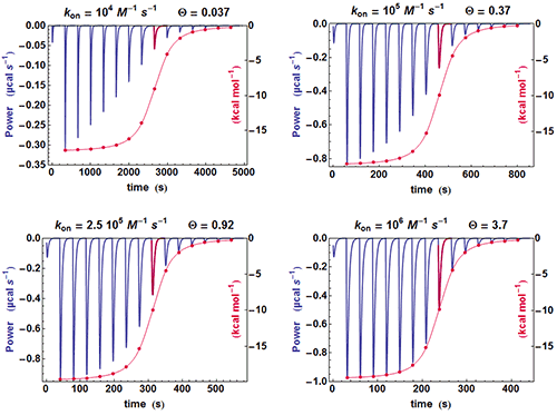
A simple method can be used for judging at a glance if some kinetic information is present in an ITC experiment. If the shapes of the successive injections remain unchanged (apart for a variable amplitude), then the full amplitude of each injection is just proportional to its integrated value, whereas if the shape of the injections change significantly, this proportionality is lost. This is illustrated in Fig. 2 with different calculated data sets with
k
on
evolving from 10
4
to 10
6
M
-1
s
-1
and
Kd
of 100 nM. It is clearly seen that when the kinetics becomes very fast (
k
on
=10
6
M
-1
s
-1
), the equilibration time for each injection is constant since it is essentially governed by
τ
ITC
(the instrument responds too slowly) and the curve obtained from the properly scaled integrated heats envelopes almost exactly the shape drawn from the tip of each injection curve. On the contrary, there is an increasing departure between the two curves when
k
on
becomes smaller and smaller, i.e. when a kinetic signal is more and more visible. The comparison of these two curves is made systematically by AFFINImeter.

|
It was shown in [9] (Supplementary Information) how an analysis based upon equation (2) describes reasonably well the variation of the equilibration time, θk , from injection to injection. An estimate of the characteristic time τ of return to baseline for any injection was obtained as:
 (5)
(5)
|
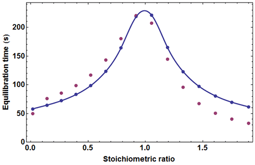
where c=[A]0/Kd is the Wieseman parameter and s=[B]tot /[A]tot is the stoichiometric ratio for the current injection. In fact, the return to baseline is not exponential due to the bimolecular character of the reaction, which means that a single time τ cannot represent exactly the whole return to baseline. However, τ given by equation (5) is practically useful because it is equal to the slowest component of this return to baseline. To take into account approximately the instrument response time, τ should be increased by τITC . One has thus to consider a time interval equal to some multiple of (τ+τITC) to reach in practice, if not in theory, the end of the injection. We found that a good choice is 4.5(τ+τITC). Finally, the latter estimate should also be increased by the injection time tinject, which can amount to a few seconds. By comparing the effective length of each injection to the theoretical expectation derived from 4.5(τ+τITC)+tinject one can then determine koff, and thus also kon since Kd is known. The ‘equilibration-time curve’ (ETC) obtained with the calculated data of Figure 1 is shown in Figure 3.

|
It appears that the exact times θ
k
derived from numerical simulation are in reasonable agreement with those derived from equation (5). One may thus utilize the times θ
k
obtained experimentally from kinITC model in AFFINImeter to assess
k
on
and
k
off
as soon as the
dissociation constant
has been obtained. It should be emphasized that
k
off
is the only free parameter for fitting an experimental ETC with equation (5), which makes this procedure extremely robust. Note that analogous considerations were described in [11].
An experimental ETC offers a remarkably simple method to estimate koff. From equation (5) it can be derived for an ideal instrument (i.e. with a null response time) koff ≈θ1/θ2max, θ1 and θmax being defined in Figure 1. Taking into account the response time leads to the rough estimate koff ≈(θ1-4.5τITC)/(θmax-4.5τITC)2 This means that by mere visual inspection of an experimental ETC, without any knowledge of the results from the usual processing, a rough estimate of koff can be obtained. Because the method is so attractive by its simplicity, one should recall that it is only valid as far as the simple kinetic scheme of equation (1) is valid. Also, one should not expect reliable results with noisy ETC, particularly if the maximum of the ETC is not clear. Applying this quick method to the theoretical data of Figure 1 leads to koff ≈ (59-4.5×3.5)/(221-4.5×3.5)2=1.02×10-3s-1 which is here very close to the value of 10-3 s-1 used in the simulation.
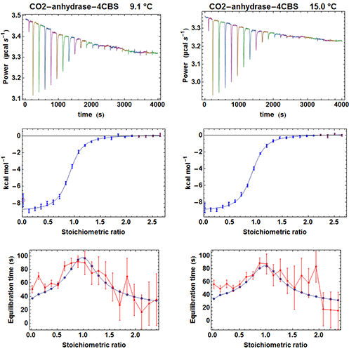
To test the efficiency of the simplified kinITC method consisting in fitting the shape of an experimental ETC with equation (5), we have considered the binding of the inhibitor 4-CBS to carbonic anhydrase. This experimental system was very well characterized by Surface Plasmon Resonance (SPR) after a benchmark involving several laboratories [12]. We have thus performed ITC experiments with an MicroCal ITC200 in the same conditions as those described in the SPR study, apart for a different set of temperatures and higher enzyme and inhibitor concentrations. The MicroCal ITC200 was operated in the high-gain mode and the stirring speed was 1000 rpm. Carbonic anhydrase and 4-CBS were purchased from Sigma and the enzyme prepared as indicated in [12]. We performed five experiments at 6.1, 9.1, 12.1, 15 and 25 °C with the enzyme in the measurement cell (compound A). The initial concentrations of the enzyme were [A]0 = 26 µM (apart for 19 µM at 25 °C) and the initial concentrations of the inhibitor in the titration syringe were [B]0 = 315 µM at all temperatures. The injected volumes were 0.3 µl for the first injection and 1.9 µl for the following injections (apart for 1.4 µl at 25 °C). Each injection was made at 0.5 µl s-1. Note that the integration time (i.e. the time between successive power measurements) was set to 2 s, which is significantly less than the default of 5 s. This is important to allow sufficient sampling of the rapidly varying part of the heat power just after the beginning of the injection (note that with the new MicroCal PEAQ-ITC instrument, this is no more an issue since power data are always sampled at 1 Hz). A subset of the results for the raw injection curves, the titration curves and the ETCs is shown in Figure 4.

|
From the fit of the experimental ETCs we obtained kon and koff at all temperatures and we compared these values with those from SPR with two Arrhenius plots (Figure 5). It appears first that the lines from kinITC and SPR for 1n kon vs. T-1 on one hand, and for 1n koff vs. T-1 on the other hand, if not superimposed, are parallel within experimental errors. This means that the ratios konSPR / konkinITC and koffSPR / koffkinITC vary little between 6 and 25 °C (konSPR / konkinITC ≈ koffSPR / koffkinITC ≈ 2) even though kon varies 2.4 fold and koff varies 5.5 fold in the temperature range common to the two experiments. For example, the values at 6 °C were:
k on SPR = (1.5±0.2)×10 4 M -1 s -1 , k on kinITC = (0.69±0.07)×10 4 M -1 s -1
k off SPR = (4.3±0.4)×10 -3 s -1 , k off kinITC = (2.8±0.3)×10 -3 s -1
and at 24 °C :
k on SPR = (3.5±0.4)×10 4 M -1 s -1 , k on kinITC = (1.4±0.16)×10 4 M -1 s -1
k off SPR = (32±3)×10 -3 s -1 , k off kinITC = (14±2)×10 -3 s -1
(the latter kinITC values were extrapolated from 25 °C).
The temperature dependences of kon and koff were thus perfectly determined by kinITC, which implies that the activation energies ΔHon× and ΔHoff× from the two techniques are identical within experimental errors (see Figure 5). This also implies that the dissociation constants KdSPR and KdITC are virtually identical at all temperatures (which was verified in [12] at only one temperature). The systematic difference by a factor of 2.5 (well beyond experimental errors) between the kinetic parameters from kinITC and SPR is, at present, without explanation. Notably, it did not result from the using of the simplified ETC-based kinITC technique since we obtained essentially the same results (not shown) by using the complete kinITC technique described in [9], that is by fitting simultaneously the shape of all injection curves of all experiments.

|
The simplified ETC-based kinITC technique proved to be efficient to provide us with kinetic information along with indisputable thermodynamic information. The great advantage of kinITC is obviously that it does not require any particular preparation of the sample and, also, that it is both a true ‘label-free’ and true ‘in-solution’ technique. On a practical ground, the algorithms introduced in AFFINImeter allow obtaining instantaneously the kinetic parameters as soon as the raw injection curves have been processed. Obviously, it will be worth examining in details the reason(s) of the systematic difference observed between kinITC and SPR results for the carbonic anhydrase/4CBS system.
We have examined through numerical simulations the inherent limitations due to the finite response time of the instrument (Fig. 2). In the original publication [9], a quantitative criterion was obtained through the dimensionless parameter Θ:
Θ = (koffkon [A]0)1/2τITC = koff c1/2τITC (6)
In agreement with the numerical simulations, it can be said that Θ should be less than 1. In practice, the exact maximum value to be considered is not universal since it depends on the quality of the injection curves. It thus depends on the ΔH of the reaction, but also crucially on all experimental aspects affecting this quality, particularly the strict identity of buffers in the measurement cell and in the syringe, and a strict respect of the cleaning procedures of the instrument. In the absence of additional investigation, it is safer to consider Θ < 0.5 . The Θ values obtained for the carbonic anhydrase ranged from 0.08 at 6.1 °C to 0.23 at 25 °C, in perfect agreement with the above criterion.
Finally, we want to stress two important points. Firstly, kinITC (as all other kinetic techniques) is model-dependent. One has to recall that thermodynamics alone cannot help distinguishing two alternative kinetic mechanisms and, therefore, that it may be necessary to prove by independent means the validity of the kinetic model in use. Of course, the full kinITC technique (with simultaneous fit of all injection curves for all experiments) can be one of these means, but it may not be sufficient to obtain a clear-cut answer on two alternative models. Secondly, it should be recalled that a two-step kinetic scheme (if experimentally validated) is amenable to kinITC [9], but only with the full kinITC technique. The method was used successfully for studying kinetic regulation of the expression of genes by so-called ‘riboswitches’ located in the upstream untranslated region (5’-UTR) of bacterial mRNAs. This was first exposed in [9] and other results are to be published soon. These methods will also be made available in AFFINImeter.
Tian, A., Mesure des intensités des petites sources de chaleur: emploi d'un microcalorimètre à compensation. C.R.A.S. (Paris), 1924. 178: p. 705-707.
Tian, A. and J. Cotie, Utilisation en biologie de la méthode microcalorimétrique; exemple d'application. C.R.A.S. (Paris), 1924. 178: p. 1390-1392.
Calvet, E. and H. Prat, Recent progress in microcalorimetry. 1963, Oxford: Pergamon Press.
Lopez-Mayorga, O., P.L. Mateo, and M. Cortijo, The use of different input signals for dynamic characterisation in isothermal microcalorimetry. J. Phys. E; Sci. Instrum., 1987. 20: p. 265-269.
Garcia-Fuentes, L., C. Baron, and O.L. Mayorga, Influence of dynamic power compensation in an isothermal titration microcalorimeter. Anal. Chem., 1998. 70: p. 4615-4623.
Willson, R.J., et al., Determination of thermodynamic and kinetic parameters from isothermal heat conduction microcalorimetrey: application to long-term-reaction studies. J. Phys. Chem., 1995. 99: p. 7108-7113.
Bianconi, M.L., Calorimetry of enzyme-catalyzed reactions. Biophysical Chemistry, 2007. 126: p. 59-64.
Vander Meulen, K.A. and S.E. Butcher, Characterization of the kinetic and thermodynamic landscape of RNA folding using a novel application of isothermal titration calorimetry. Nucleic Acids Res, 2012. 40(5): p. 2140-51.
Burnouf, D., et al., kinITC: a new method for obtaining joint thermodynamic and kinetic data by isothermal titration calorimetry. J Am Chem Soc, 2012. 134(1): p. 559-65.
Tachoire, H., J.L. Macqueron, and V. Torra, Traitement du signal en microcalorimétrie: applications en cinétique et thermodynamique. Thermochimica Acta, 1986. 105: p. 333-367.
Egawa, T., et al., Method for determination of association and dissociation rate constants of reversible bimolecular reactions by isothermal titration calorimeters. Analytical Chemistry, 2007. 79: p. 2972-2978.
Navratilova, I., et al., Thermodynamic benchmark study using Biacore technology. Anal Biochem, 2007. 364(1): p. 67-77.